Steel Roll Cage
(2021-2022)


Competition Summary
The Great Northern Concrete Toboggan Race is a Canadian engineering competition where teams design a toboggan that can transport 5 people down a hill, have all surfaces contacting the ground made of concrete, have functional steering and braking systems, and a completely enclosed roll cage. Each team also picks a theme for the competition and presents it with a display at the technical exhibition and through costumes, cheers, and presentations.
As the 2021-2022 roll cage captain for the McMaster Engineering Concrete Toboggan Team, my responsibility was to design and fabricate a roll cage that is capable of withstanding any foreseeable crash impacts and protects all riders. Design parameters such as toboggan speed, impact time, and weight were given in the competition rules, and the effectiveness of the roll cage is required to be proven in a safety report.
Design Process
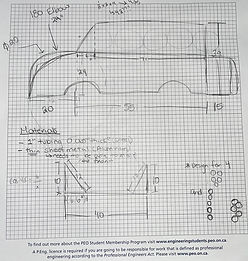
Brainstorm Design
During the initial brainstorming, I focused on creating a design that encompassed aerodynamics and representation of the theme. Since our theme was Barbie, I wanted to create a roll cage that resembles Barbie's pink convertible.

3D Model Design
Creating the beginning revisions in Solidworks 2021 allowed me to map out dimensions and make sure everything was proportional. This also allowed me to determine the feasibility of the design. Since I would be fabricating it myself and using the workshop at school, I was limited to the machines in the workshop and the amount of time during the year that I had to learn how to use them.


Material Choice
In Revision 6 I used round tubing, however, it was determined that given the machines I had access to, it would be much more feasible to use square tubing. 1" SQ x 0.065" and 3/4" SQ x 0.083" AISI 1020 steel tubing was chosen for its high strength properties and because we could get it sponsored through Russel Metals. 1" SQ x 0.065" tubing was chosen as the main frame of the superstructure, while 3/4" SQ x 0.083" tubing was used as the side members because it is slightly lighter but maintained the right strength.

Finite Element Analysis
I took the impact duration, speed, and weight of the toboggan given by the Safety Committee for front and rear impact, side impact, and rollover impact, and converted them into equivalent static forces to find stress analysis, displacement, and factor of safety plots. I used the results of these plots to adjust the structure of the roll cage until it was safe (Displacement<6mm, FOS>2.0). As can be seen in design revisions 15 and 18 above, some of the members were taken out for the final design because I determined they were unnecessary given the results of the FEA. This ensured the roll cage was as light as safely possible.
Finite Element Analysis Results for Front Impact
The front impact scenario is the most likely impact scenario to occur. An equivalent force of 20.452 kN was applied to the front face of the toboggan to simulate a stopping time of 0.5 seconds, impact speed of 60km/hr, and toboggan mass of 612.35kg. The pictures to the right show maximum stress of 171.5 MPa, maximum deformation of 5.069 mm, and a minimum factor of safety of 2.1. The deformation will occur in the front crumple zone, with no risk to the passengers. The combination of these results with overestimated calculations determined the frame will not fail in this loading scenario.


Cut and Tack Weld Roll Cage Together
Over the span of 3 months, I went into the workshop to cut the steel members and tack weld them together. For the easier cuts, I held cutting sessions with general members of the team to teach them how to cut steel using the gravity bandsaw and sand the sharp edges down with a vertical belt sander. All of the MIG welding and setups were done by myself. Please see the fabrication process below.


Stitch Weld Toboggan
The next step was to stitch weld all of the joints of the toboggan. Overall it took about 4 hours to complete. Two of the compound angle members were not completely flush together, leaving gaps of up to 1/8in. I used tack welds to fill the gap in and make it a safely sealed weld (see second complex joint picture). While not all welds looked like perfect stitch welds, they all went through and successfully/safely welded the joints together.
Complex Joint


Simple Joint


Welding Video
Stitch Welds From Welding Video
Note: For the second weld in the Welding Video, the tack welded members had a small gap, interrupting the welding arc. It can be seen in the Stitch Weld from Welding Video that I filled the rest in afterward.
Assemble All Other Components
Unfortunately, the competition was canceled, and we did not get the chance to completely assemble the toboggan. Although the roll cage was complete, the team did not get to fully attach the breaks, steering system, or skis. Below are pictures of the fully assembled toboggan in Solidworks with and without theme additions.

